Deja un mensaje
Si está interesado en nuestros productos y desea obtener más información, deje un mensaje aquí, le responderemos lo antes posible.

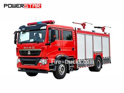
Manual de reparación del motor del camión de bomberos Isuzu NPR 4HK1
El Manual de mantenimiento del motor del camión de bomberos Isuzu 4HK1-TC, también llamado Manual de reparación del motor Camión de bomberos Isuzu o Libro de ingeniero de Vehículo de extinción de incendios Isuzu .
El motor del camión de bomberos Isuzu 4HK1-TC es un motor diésel de alto rendimiento ampliamente utilizado en camiones de bomberos, reconocido por su fiabilidad, durabilidad y alta eficiencia. Para garantizar su funcionamiento estable a largo plazo, es fundamental realizar un mantenimiento y una reparación regulares. Este artículo presenta brevemente el contenido principal del Manual de Mantenimiento del Motor del Camión de Bomberos Isuzu 4HK1-TC para facilitar su comprensión y manejo.
1. Descripción general del motor
El motor 4HK1-TC es un motor diésel turboalimentado de 4 cilindros en línea con una cilindrada de 5,2 litros y una potencia máxima de 190 CV. Utiliza un avanzado sistema de inyección de combustible common rail y una unidad de control electrónico (ECU) para lograr una mayor eficiencia de combustible y menores emisiones.
2. Mantenimiento diario
El mantenimiento diario es fundamental para garantizar el funcionamiento normal del motor. El manual de mantenimiento detalla las inspecciones diarias, como la revisión del nivel de aceite y refrigerante, la limpieza o sustitución del filtro de aire y el cambio del filtro de combustible. Además, el manual también ofrece recomendaciones para la sustitución regular del aceite y el filtro de aceite del motor, generalmente cada 5000 kilómetros o cada 6 meses.
3. Diagnóstico de fallas
El manual de mantenimiento contiene un proceso detallado de diagnóstico de fallas para ayudar al personal de mantenimiento a localizar y resolver problemas rápidamente. El manual enumera los códigos de falla comunes y sus significados, y ofrece las soluciones correspondientes. Por ejemplo, si el motor tiene poca potencia, el manual guiará al personal de mantenimiento para revisar el sistema de combustible, el turbocompresor y el sistema de escape, etc.
4. Revisión y reemplazo de piezas
Para motores que requieren revisión o reemplazo de piezas, el manual de mantenimiento detalla los pasos y precauciones. Por ejemplo, al reemplazar componentes clave como anillos de pistón, guías de válvulas y cojinetes, el manual detalla los pasos de extracción e instalación, así como las herramientas necesarias y las especificaciones de torque.
5. Precauciones de seguridad
El manual de mantenimiento hace especial hincapié en la importancia de una operación segura. Antes de realizar cualquier operación de mantenimiento, asegúrese de que el motor se haya enfriado completamente y de que la fuente de alimentación esté desconectada. Además, el manual también ofrece recomendaciones para el uso de equipo de protección personal, como guantes, gafas protectoras y ropa de protección.
Sección 1A
Sistema de control del motor
Tabla de contenido
Página
[si supportFields]> TOC \h \z \t "1A,1,1A-,2"
Sistema de control del motor
[si supportFields]>
4
[si gte mso 9]>
Precauciones
[si supportFields]>
4
[si gte mso 9]>
Función y principio de funcionamiento
[si supportFields]>
5
[si gte mso 9]>
Diagrama de configuración de piezas
[si supportFields]>
21
[si gte mso 9]>
Diagrama de circuito
[si supportFields]>
25
[si gte mso 9]>
Cómo diagnosticar la falla
[si supportFields]>
42
[si gte mso 9]>
Procedimientos de operación de diagnóstico de fallas a través del medidor de diagnóstico de fallas
[si supportFields]>
48
[si gte mso 9]>
Descripción general de la comprobación funcional
[si supportFields]>
50
[si gte mso 9]>
Consulta
[si supportFields]>
51
[si gte mso 9]>
Comprobación del sistema de control del motor
[si supportFields]>
53
[si gte mso 9]>
Lista de datos del medidor de diagnóstico de fallas
[si supportFields]>
55
[si gte mso 9]>
Contenido de la lista de datos del medidor de diagnóstico de fallas
[si supportFields]>
58
[si gte mso 9]>
Salida del medidor de diagnóstico de fallas
[si supportFields]>
64
[si gte mso 9]>
Diagnóstico de fallas en el inicio del medidor
[si supportFields]>
65
[si gte mso 9]>
Falla de comunicación del medidor de diagnóstico de fallas (referencia)
[si supportFields]>
67
[si gte mso 9]>
Fallo de comunicación con el ECM (referencia)
[si supportFields]>
71
[si gte mso 9]>
Confirmación del sistema de arranque
[si supportFields]>
74
[si gte mso 9]>
Confirmación del sistema del circuito eléctrico de iluminación de la luz MIL del motor
[si supportFields]>
77
[si gte mso 9]>
Confirmación del sistema del circuito eléctrico con luz intermitente del motor MIL
[si supportFields]>
78
[si gte mso 9]>
Inspección del sistema de control de recirculación de gases de escape (EGR)
[si supportFields]>
80
[si gte mso 9]>
Inspección del sistema de control de calentamiento
[si supportFields]>
84
[si gte mso 9]>
Inspección del sistema de control de restricción de entrada de aire/freno de escape
[si supportFields]>
87
[si gte mso 9]>
Descripción general del código de diagnóstico de problemas (DTC)
[si supportFields]>
92
[si gte mso 9]>
DTC P0016 (Código de destello 16)
[si supportFields]>
95
[si gte mso 9]>
DTC P0087 (Código de destello 225)
[si supportFields]>
97
[si gte mso 9]>
DTC P0088 (Código de destello 118)
[si supportFields]>
103
[si gte mso 9]>
DTC P0089 (Código de destello 151)
[si supportFields]>
109
[si gte mso 9]>
DTC P0091, P0092 (Código de destello 247)
[si supportFields]>
112
[si gte mso 9]>
DTC P0093 (Código de destello 227)
[si supportFields]>
116
[si gte mso 9]>
DTC P0107, P0108 (Código de destello 32)
[si supportFields]>
122
[si gte mso 9]>
DTC P0112, P0113 (Código de destello 22)
[si supportFields]>
127
[si gte mso 9]>
DTC P0117, P0118 (Código de destello 23)
[si supportFields]>
132
[si gte mso 9]>
DTC P0122, P0123 (Código de destello 43)
[si supportFields]>
137
[si gte mso 9]>
DTC P0182, P0183 (Código de destello 211)
[si supportFields]>
142
[si gte mso 9]>
DTC P0192, P0193 (Código de destello 245)
[si supportFields]>
147
[si gte mso 9]>
[si admite campos]> DTC P0201, P0202, P0203, P0204 (Código de destello 271, 272, 273, 274)................................................ 1A-157
DTC P0217 (Código de destello 542).................................................................................................. 1A-170
DTC P0219 (Código de destello 543)................................................................................................. 1A-172
DTC P0234 (Código de destello 42).................................................................................................. 1A-175
DTC P0299 (Código de destello 65).................................................................................................. 1A-178
DTC P0335 (Código de destello 15).................................................................................................. 1A-182
DTC P0336 (Código de destello 15).................................................................................................. 1A-187
DTC P0340 (Código de destello 14).................................................................................................. 1A-190
DTC P0341 (Código de destello 14).................................................................................................. 1A-195
DTC P0380 (Código de destello 66).................................................................................................. 1A-198
DTC P0381 (Código de destello 67).................................................................................................. 1A-201
DTC P0404 (Código de destello 45).................................................................................................. 1A-205
DTC P0409 (Código de destello 44).................................................................................................. 1A-208
DTC P0477, P0478 (Código de destello 46)................................................................................... 1A-212
DTC P0500 (Código de destello 25).................................................................................................. 1A-216
DTC P0502, P0503 (Código de destello 25)................................................................................... 1A-218
DTC P0563 (Código de destello 35)................................................................................................. 1A-223
DTC P0601 (Código de destello 53).................................................................................................. 1A-225
DTC P0602 (Código de destello 154).................................................................................................. 1A-226
DTC P0604, P0606, P060B (Códigos de destello 153, 51, 36).................................................................... 1A-228
DTC P0641 (Código de destello 55)................................................................................................. 1A-230
DTC P0650 (Código de destello 77).................................................................................................. 1A-233
DTC P0651 (Código de destello 56).................................................................................................. 1A-237
DTC P0685, P0687 (Código de destello 416).......................................................................................... 1A-241
DTC P0697 (Código de destello 57).................................................................................................. 1A-245
DTC P1093 (Código de destello 227).................................................................................................. 1A-248
DTC P1261, P1262 (Código de destello 34)................................................................................... 1A-253
DTC P1404 (Código de destello 45).................................................................................................. 1A-255
DTC P1621 (Código de destello 54).................................................................................................. 1A-257
DTC P2122, P2123 (Código de destello 121).......................................................................................... 1A-258
DTC P2127, P2128 (Código de destello 122).......................................................................................... 1A-264
DTC P2138 (Código de destello 124).................................................................................................. 1A-270
DTC P2146, P2149 (Código de destello 158)................................................................................... 1A-273
DTC P2228, P2229 (Código de destello 71)................................................................................... 1A-279
DTC P253A (Código de destello 28)................................................................................................. 1A-284
DTC P256A (Código de destello 31)................................................................................................. 1A-287
DTC U0073 (Código de destello 84).................................................................................................. 1A-291
Diagnóstico de síntomas.................................................................................................................. 1A-296
Fenómenos: Intermitencia................................................................................................................ 1A-297
Síntoma: Arranque difícil............................................................................................................. 1A-300
Fenómenos: Sobretensión, ralentí inestable o calado del motor..................................................................................... 1A-303
Fenómenos: Ralentí alto.................................................................................................................. 1A-306
Síntoma: Parada de emergencia............................................................................................................. 1A-307
Síntoma: Cambio de emergencia.................................................................................................. 1A-309
Síntoma: Baja potencia, fallo de aceleración o retraso en la respuesta........................................................... 1A-311
Fenómenos: Funcionamiento intermitente, fallo de aceleración.................................................................... 1A-314
Síntoma: Ruido de combustión............................................................................................................ 1A-316
Síntoma: Bajo consumo de combustible.................................................................................................. 1A-317
Fenómenos: humo negro procedente de los gases de escape............................................................................. 1A-319
Síntoma: Humo blanco en los gases de escape.................................................................................. 1A-321
Parámetros principales del sensor............................................................................................................. 1A-323
Herramientas especiales.................................................................................................................. 1A-325
Programa................................................................................................................................ 1A-326
Regla de programación................................................................................................................. 1A-326
Programa................................................................................................................................ 1A-326
Aprendizaje de la bomba de inyección.................................................................................................. 1A-328
Ajuste............................................................................................................................................ 1A-328
Uso de herramientas de prueba de circuitos
Si se realiza un diagnóstico según el programa de diagnóstico, no utilice la lámpara de prueba para el diagnóstico del sistema eléctrico del tren de potencia a menos que se especifique lo contrario. Si se va a utilizar el terminal de la sonda para el programa de diagnóstico, utilice el kit adaptador de prueba de terminales 5-8840-2835-0.
Componente eléctrico disponible en el mercado
Los componentes eléctricos disponibles en el mercado son aquellos que se adquieren para su instalación en el vehículo. Dado que estos componentes no se tienen en cuenta durante el diseño del vehículo, es importante prestarles atención al usarlos.
Precaución:
La alimentación y la tierra de los componentes eléctricos disponibles en el mercado deben conectarse al circuito independiente del circuito del sistema de control eléctrico.
Aunque se pueden utilizar componentes eléctricos disponibles en el mercado, estos pueden causar fallos de funcionamiento del sistema de control eléctrico en algunos casos. Esto incluye dispositivos no conectados al sistema eléctrico, como el teléfono móvil o la radio. Por lo tanto, al realizar el diagnóstico del tren motriz, primero verifique si dichos componentes eléctricos disponibles en el mercado están instalados. De ser así, retírelos del vehículo. Si la falla persiste después de retirar el componente, siga el procedimiento general de diagnóstico.
Daños por ESD
Dado que los componentes electrónicos del sistema de control eléctrico pueden funcionar a voltajes extremadamente bajos, son propensos a sufrir daños por ESD. Algunos componentes electrónicos se dañan por la electricidad estática por debajo de 100 V, imperceptible para el ser humano. La ESD perceptible para el ser humano requiere un voltaje de 4000 V. En muchos casos, el ser humano es portador de la electricidad estática, siendo la fricción y la electrificación por inducción las más comunes.
● Cuando el humano se mueve de un lado a otro en el asiento, se generará la electrificación por fricción.
● Cuando una persona con calzado aislante se acerca a un objeto altamente electrificado, se produce inducción electrostática al tocar el suelo. La persona se electrifica cuando las cargas de la misma polaridad entran en contacto con las de polaridad opuesta. Dado que la electricidad estática puede causar daños, manipule con cuidado los componentes electrónicos y pruébelos.
Precaución:
Tenga en cuenta las siguientes reglas para evitar daños debidos a ESD:
● No toque los pines de contacto del terminal ECM ni las partes electrónicas soldadas a la placa posterior del circuito ECM.
● No desembale los parques a menos que la preparación de la instalación de las piezas haya finalizado.
● Conecte el paquete y la tierra normal del vehículo antes de sacar las piezas del paquete.
● Si se mueve de un lado a otro en el asiento, o se sienta desde una posición de pie o maneja la pieza mientras se mueve a cierta distancia, asegúrese de tocar el suelo normal antes de instalar la pieza.
Función y principio de funcionamiento
Sistema de control del motor (common rail)
Descripción general y detalles del sistema
El sistema de control del motor es el sistema de control eléctrico que controla el motor para alcanzar el estado de combustión óptimo según las condiciones de conducción. Consta de las siguientes partes:
● Sistema de inyección de combustible controlado electrónicamente (tipo common rail)
● Recirculación de gases de escape
Además, el sistema de control del motor incluye las siguientes funciones de control del sistema.
● Sistema de control de calentamiento
● Salida rotativa del motor
● Función de comunicación y autodiagnóstico
[fin si]
[si gte vml 1]>
Sistema de inyección de combustible controlado electrónicamente (tipo common rail)
El sistema common rail consta de una cámara de presión y un inyector. La cámara de presión, denominada common rail, almacena el combustible presurizado; el inyector, a su vez, incorpora una electroválvula de control electrónico para inyectar el combustible presurizado en la cámara de combustión. Dado que el control de la inyección (presión, caudal y tiempo de inyección) se controla mediante la ECM, el sistema common rail permite controlar de forma independiente la velocidad y la carga del motor. Incluso a bajas revoluciones, se mantiene una presión de inyección estable, lo que reduce considerablemente la emisión de humo negro al arrancar y acelerar el motor diésel. Gracias a este control, los gases de escape se purifican, el volumen de escape se reduce y la potencia es mayor.
Control del volumen de inyección
Controla el bobinado del inyector de acuerdo a la señal obtenida de la velocidad del motor y la apertura del pedal del acelerador y en consecuencia controla el volumen de inyección de combustible para lograr el mejor volumen.
Control de la presión de inyección
Para permitir la inyección a alta presión incluso a baja velocidad del motor, se debe controlar la presión de combustible en el conducto común. Determine la presión adecuada en el conducto común según la velocidad del motor y el volumen de inyección, descargue la cantidad correcta de combustible a través de la bomba de inyección de control y aliméntelo al conducto común bajo presión.
Control del tiempo de inyección
Sustituye la función de sincronización y calcula el tiempo de inyección de combustible apropiado según la velocidad del motor y el volumen de inyección y luego controla el inyector.
Control de la tasa de inyección
Para mejorar la eficiencia de la combustión del cilindro, inyecte (preinyección) un poco de combustible para el encendido. Tras el encendido, realice la segunda inyección (inyección principal). Controle el tiempo y el volumen de inyección mediante el inyector (la bobina del inyector).
 [fin si]
Sistema de combustible
El sistema common rail consta de 2 sistemas de presión de combustible.
● Línea de entrada de baja presión: entre el tanque de combustible y la bomba de inyección
● Línea de alta presión: entre la bomba de inyección y el inyector
El combustible es aspirado por la bomba de inyección desde el depósito y bombeado para alimentar el conducto común. En este punto, La señal del ECM controla la válvula de control de succión (el regulador de presión del riel común) para controlar el volumen de combustible suministrado al riel común.
Diagrama del sistema de combustible
[si gte vml 1]>
|
Llave 1. Riel común 2. Válvula limitadora de presión 3. Tubo de retorno del inyector 4. Inyector 5. Tubo de retorno de combustible 6. Tubería de suministro de combustible |
7. Tanque de combustible 8. Válvula de ventilación 9. Bomba de arranque 10. Filtro de combustible (con separador de aceite y agua) 11. Válvula de retorno 12. Bomba de inyección de combustible |
EGR (Recirculación de gases de escape)
El sistema EGR recicla parte de los gases de escape al colector de admisión, reduciendo así las emisiones de óxidos de nitrógeno (NOx). Gracias al sistema EGR, se mejora la conducción y se reducen las emisiones de gases de escape. La corriente de control del EGR controla el funcionamiento de la válvula solenoide y, en consecuencia, la carrera de la válvula. Además, este sistema detecta la carrera real de la válvula mediante el sensor de posición del EGR para un control preciso.
La EGR comenzará a funcionar cuando se cumplan las condiciones de velocidad del motor, temperatura del refrigerante del motor, temperatura de admisión y presión barométrica. A continuación, calculará la apertura de la válvula en función de la velocidad del motor y el volumen de inyección de combustible objetivo. Con base en la apertura calculada, determinará la carga de accionamiento de la electroválvula y la accionará. La mariposa de admisión de aire se cerrará durante el funcionamiento de la EGR para permitir que la presión interna del colector de admisión alcance el valor objetivo.
[si gte vml 1]>
[fin si]
[si !mso]
|
[fin si]
[si !mso]
|
[fin si]
[si !mso]
|
[fin si]
[si !mso]
|
|
Llave 1. Módulo de gestión del ciclo de vida (ECM) 2. Sensor de posición EGR 3. Válvula EGR 4. Enfriador de EGR |
5. Válvula de mariposa de admisión
|
Control de calentamiento
Sistema de control de calentamiento
El sistema de control de calentamiento está diseñado para facilitar el arranque del motor a baja temperatura y reducir la emisión de humo blanco y el ruido. Con el interruptor de arranque activado, el módulo de control del motor (ECM) detecta la temperatura del refrigerante del motor según la señal del sensor de temperatura del refrigerante del motor (ECT) para ajustar el tiempo de calentamiento y lograr las condiciones de arranque adecuadas para el motor. Además, el calor residual del calentamiento mantiene estable el ralentí. El ECM determina el tiempo de calentamiento según la temperatura del refrigerante del motor para activar el relé de calentamiento y la luz indicadora.
[fin si]
[si gte vml 1]>
Descripción general del control del freno de escape
El tubo de escape del freno de escape cuenta con una válvula interna. Cerrar la válvula aumenta la resistencia del escape y mejora el efecto del freno motor. La válvula del freno de escape funciona según la presión de vacío. Esta presión se controla mediante la apertura y el cierre de la válvula solenoide. El módulo de control del motor activa la válvula solenoide si la velocidad del motor supera las 575 rpm y se cumplen todas las condiciones de funcionamiento del freno de escape.
Condiciones de funcionamiento del freno de escape
● Interruptor de freno de escape activado
● Pedal del acelerador no pisado
● No se detecta sensor de posición del pedal del acelerador (APP) anormal, circuito de freno de escape anormal, interruptor de embrague anormal, interruptor del sensor APP anormal, interruptor A/D anormal, etc.
● Pedal de embrague no pisado
● Voltaje del sistema superior a 24 V
● La velocidad del vehículo excede el rango especificado
Módulo de gestión del ciclo de vida (ECM)
Descripción general de ECM
[si gte vml 1]>
El ECM monitorea constantemente la información de cada sensor para controlar el tren motriz. El ECM realiza un diagnóstico del sistema para detectar problemas de funcionamiento, avisar al conductor mediante la luz de advertencia del motor y registrar simultáneamente los códigos de falla (DTC). Los DTC identifican la zona problemática para ayudar al personal de mantenimiento.
Funciones del ECM
El módulo de control electrónico (ECM) exporta 5 V de voltaje para alimentar diversos sensores e interruptores. Sin embargo, dado que la energía proviene de la resistencia del ECM, la lámpara de prueba conectada al circuito no se encenderá incluso si la resistencia es muy alta. En algunos casos, el voltímetro común no puede mostrar la lectura correcta debido a que su resistencia es demasiado baja. Para obtener una lectura correcta, asegúrese de usar un multímetro digital con una impedancia de entrada de al menos 10 MΩ (5-8840-2691-0). El ECM controla el circuito de tierra o de alimentación a través del transistor u otra unidad y, en consecuencia, controla el circuito de salida.
Piezas de ECM y composición
El módulo de control electrónico (ECM) puede lograr una alta maniobrabilidad y eficiencia de combustible, manteniendo el nivel de gases de escape especificado. El ECM monitorea el rendimiento del motor y del vehículo mediante el sensor de posición del cigüeñal (CKP) y el sensor de velocidad del vehículo (VSS), entre otros.
Descripción del voltaje del ECM
El módulo de control electrónico (ECM) aplica el voltaje estándar a cada interruptor y sensor. Esto se debe a que la resistencia del ECM es muy alta, mientras que el voltaje aplicado al circuito es bajo. La lámpara de prueba no se encenderá incluso si está conectada al circuito. Dado que la impedancia de entrada del voltímetro, generalmente utilizado por el personal de mantenimiento, es muy baja, a veces no muestra la lectura correcta. En tal caso, utilice un multímetro digital con una impedancia de entrada de 10 MΩ (5-8840-2691-0) para obtener la lectura correcta del voltaje.
La unidad de entrada/salida del ECM está equipada con un convertidor analógico-digital, atenuador de señal, contador y actuador especial. El ECM puede controlar la mayoría de los componentes mediante un interruptor electrónico.
EEPROM
La EEPROM es un chip de almacenamiento permanente soldado a la placa posterior del ECM. Para controlar el tren de potencia, el ECM transmite el programa y el mensaje de calibración necesarios a la EEPROM.
A diferencia de la ROM, la EEPROM no se puede reemplazar. Si se detecta una anomalía en la EEPROM, reemplace directamente el ECM.
Consideraciones para la reparación del ECM
El módulo de control electrónico (ECM) puede soportar la corriente general necesaria para la conducción del vehículo. Evite la sobrecarga del circuito. Durante las pruebas de circuito abierto y cortocircuito, no conecte el circuito del ECM al cable de tierra ni aplique voltaje a menos que se especifique lo contrario. Para estas pruebas, utilice el multímetro digital (5-8840-2691-0).
 [fin si]
La bomba de inyección es el componente principal del sistema de inyección electrónica de combustible Common Rail. Está instalada en la parte delantera del motor. El regulador de presión Common Rail y el sensor de temperatura del combustible (FT) forman parte de la bomba de inyección.
El combustible se alimenta a la bomba de inyección desde el tanque de combustible a través de la bomba de suministro interna (tipo rotor). La bomba de suministro alimenta el combustible a 2 compartimentos de émbolo en la bomba de inyección. El combustible alimentado al compartimento del émbolo es regulado por el regulador de presión del riel común. El regulador de presión del riel común solo es controlado por la corriente de suministro del ECM. El flujo de combustible alcanzará el máximo si no se alimenta corriente a la válvula solenoide. Por el contrario, el combustible dejará de fluir cuando la corriente de la válvula solenoide alcance el máximo. A medida que el motor gira, los dos émbolos generan alta presión en el riel común. Controla el regulador de presión del riel común de acuerdo con la señal del ECM y, en consecuencia, controla el volumen y la presión de combustible al riel común. De esta manera, se puede lograr el estado de funcionamiento óptimo para mejorar la eficiencia económica de combustible y reducir la emisión de NOx.
[si gte vml 1]>
Llave
1. Sensor de temperatura del combustible (FT)
2. Válvula de control de succión (regulador de presión del riel común)
Válvula de control de succión (regulador de presión del riel común)
El ECM controla el factor de carga del regulador de presión del riel común (el tiempo de encendido del regulador) para regular el volumen de combustible que se alimenta al émbolo de alta presión. Para lograr la presión deseada en el riel, se debe suministrar la cantidad adecuada de combustible para reducir la carga de accionamiento de la bomba de inyección. Cuando se alimenta corriente al regulador de presión del riel común, se genera la fuerza electromotriz variable correspondiente al factor de carga para variar la apertura de la línea de combustible y, en consecuencia, ajustar el volumen de combustible. Cuando se apaga el regulador de presión del riel común, el resorte retráctil se retrae, la línea de combustible se abre completamente y el combustible fluye hacia el émbolo (la admisión máxima y la descarga máxima). Con el regulador de presión del riel común abierto, la línea de combustible se cierra (normalmente abierta) bajo la función del resorte retráctil. A través de la apertura y el cierre del regulador de presión del riel común, se suministra el combustible correspondiente a la tasa de carga de trabajo y luego se descarga desde el émbolo.
Sensor de temperatura del combustible (FT)
El sensor FT se instala en la bomba de inyección y el termistor modifica la resistencia según la variación de temperatura. La resistencia será baja si la temperatura del combustible es alta y alta si es baja. El módulo de control del motor (ECM) aplica 5 V al sensor FT a través de la resistencia de carga y calcula la temperatura del combustible según la variación de voltaje para controlar la bomba de inyección. El voltaje será bajo si la resistencia es baja (temperatura alta) y alto si es alta (temperatura baja).
carril común
[si gte vml 1]>
Llave
1. Válvula limitadora de presión
2. Sensor de presión del riel común
Gracias al sistema de inyección de combustible con control eléctrico de riel común, este se encuentra entre la bomba de inyección y el inyector para almacenar el combustible a alta presión. El sensor de presión y la válvula limitadora de presión están instalados en el riel común. El sensor de presión detecta la presión de combustible en el riel común y transmite la señal al módulo de control del motor (ECM). Con base en esta señal, el ECM controla la presión de combustible en el riel común mediante el regulador de presión del riel común de la bomba de inyección. Si la presión de combustible en el riel común es demasiado alta, la válvula limitadora de presión se abre para liberarla.
Sensor de presión del riel común
El sensor de presión del conducto común se instala en el conducto común para detectar la presión de combustible y convertirla en una señal de voltaje. A mayor presión, mayor voltaje; a menor presión, menor voltaje. El módulo de control del motor (ECM) calcula la presión real del conducto común (presión de combustible) según la señal de voltaje del sensor para controlar la inyección de combustible.
válvula limitadora de presión
[si gte vml 1]>
Llave
1. Válvula
2. Cuerpo de la válvula
3. Guía de válvulas
4. Primavera
5. Vivienda
6. Entrada de combustible
7. Salida de combustible
En caso de una presión anormalmente alta, la válvula limitadora de presión se abrirá para liberar la presión. La válvula se abrirá cuando la presión interna del conducto común supere los 220 MPa y se cerrará cuando la presión sea inferior a 50 MPa. El combustible descargado por la válvula limitadora de presión fluirá al tanque de combustible.
Inyector
[si gte vml 1]>
Llave
1. Perno de cableado
2. Regresar al departamento de instalación de tuberías
3. Junta tórica
4. Pieza de instalación de la tubería de inyección
5. Marcado de identificación
6. Código de identificación del inyector
A diferencia de la boquilla de inyección anterior, el inyector de control eléctrico, controlado por el ECM, cuenta con un pistón de comando y una válvula solenoide. Esta información se registra en el código ID (24 dígitos) para mostrar las características del inyector. Este sistema controla el volumen de inyección para lograr el efecto óptimo con la información de flujo del inyector (código ID). Al instalar un nuevo inyector en el vehículo, asegúrese de introducir el código ID en el ECM.
Para mejorar la precisión del volumen de inyección, utilice el código de barras 2D o el código de identificación del inyector. Con este código, se puede lograr un control descentralizado del volumen de inyección en cada zona de presión para mejorar la tasa de combustión, reducir las emisiones y proporcionar una salida estable.
[fin si]
[si gte vml 1]>
● Sin inyección
Si el ECM no alimenta la válvula solenoide a través de la válvula de dos vías (TWV), cerrará el orificio de estrangulación de salida con la fuerza del pistón. En este punto, la presión de combustible aplicada al extremo delantero de la boquilla se equilibrará con la presión de combustible aplicada a la sala de control a través de la entrada. En este estado de equilibrio de presión, la suma de la presión aplicada al pistón de comando y la gravedad del pistón de la boquilla será mayor que la presión aplicada al extremo delantero de la boquilla. Por lo tanto, la boquilla se empujará hacia abajo para cerrar el orificio de inyección.
● Inyección
Si el ECM activa la válvula solenoide, la válvula TWV se activará para abrir el orificio de estrangulación de salida y el combustible fluirá al puerto de retorno de aceite. En este punto, la boquilla y el pistón de comando se elevan junto con la presión aplicada al extremo delantero de la boquilla. A continuación, el orificio de inyección de la boquilla se abrirá para inyectar el combustible.
● Extremo de inyección
Cuando el ECM deja de alimentar la válvula solenoide, la TWV disminuye y la abertura de salida se cierra. En este punto, el combustible no puede fluir al puerto de retorno desde la sala de control y la presión del combustible en el interior aumenta rápidamente. El pistón de comando presiona la boquilla para cerrar el puerto de inyección y, a continuación, se detiene la inyección de combustible.
Sensor de temperatura del refrigerante del motor (ECT)
[si gte vml 1]>
El sensor ECT se instala cerca de la carcasa del termostato y el termistor modifica su resistencia según la variación de temperatura. La resistencia será menor si la temperatura del refrigerante del motor es alta y mayor si es baja. El módulo de control del motor (ECM) aplica 5 V al sensor ECT a través de la resistencia de carga y calcula la temperatura del refrigerante del motor según la variación de voltaje para controlar la inyección de combustible. El voltaje será bajo si la resistencia es baja (temperatura alta) y alto si es alta (temperatura baja).
Sensor de posición del árbol de levas (CMP)
[si gte vml 1]>
Llave
1. Engranaje del árbol de levas
2. Dirección de rotación
3. Sensor de posición del árbol de levas (CMP)
El sensor de posición del árbol de levas (CMP) está instalado en la sección trasera de la culata. La sección de levas del árbol de levas genera la señal CMP al pasar por el sensor. El ECM determina las condiciones del cilindro y el ángulo del cigüeñal según la señal CMP y la señal CKP del sensor CKP para controlar la inyección de combustible y calcular la velocidad del motor. Aunque estos controles se basan generalmente en la señal CKP, funcionarán según la señal CMP en caso de anomalía en el sensor CKP.
Sensor de posición del cigüeñal (CKP)
[si gte vml 1]>
Llave
1. Sensor de posición del cigüeñal (CKP)
El sensor CKP está instalado en la carcasa del volante. Cuando el orificio del volante pasa a través del sensor, se genera la señal CKP. El ECM determina las condiciones del cilindro y el ángulo del árbol de levas según la señal CKP y la señal CMP del sensor CMP para controlar la inyección de combustible y calcular la velocidad del motor. Aunque estos controles se basan generalmente en la señal CKP, funcionarán según la señal CMP en caso de anomalía en el sensor CKP.
Sensor de posición del pedal del acelerador (APP) 1
[si gte vml 1]>
El sensor APP se instala en el soporte del pedal del acelerador. Este sensor consta de dos sensores en una sola carcasa. El ECM determina el valor objetivo de aceleración y desaceleración con el sensor APP. El sensor APP es un sensor de tipo pin hole 1C. El voltaje de la señal varía proporcionalmente con la variación del ángulo del pedal del acelerador. El voltaje de la señal del sensor APP 1 es bajo al principio y aumenta al pisar el pedal. El voltaje de la señal del sensor APP 2 es alto al principio y disminuye al pisar el pedal.
Sensor de velocidad del vehículo
[si gte vml 1]>
El sensor de velocidad del vehículo (VSS) está instalado en la transmisión. Este sensor cuenta con un circuito de efecto Hall. El imán y el eje de salida generan el campo magnético al girar juntos y, al interactuar con dicho campo, generan la señal de pulso.
Sensor de presión atmosférica
[si gte vml 1]>
El sensor de presión barométrica está instalado en el tablero y cambia el voltaje de la señal junto con la presión. El módulo de control del motor (ECM) detecta un voltaje bajo cuando la presión es baja en zonas de gran altitud; por el contrario, detecta un voltaje alto cuando la presión es alta. Con estas señales de voltaje, el ECM puede regular el volumen y el tiempo de inyección de combustible para corregir la altitud.
Sensor de temperatura del aire de admisión (IAT)
[si gte vml 1]>
Sensor de temperatura del aire de admisión (IAT)
El sensor IAT se instala en el tubo guía entre el filtro de aire y el turbocompresor. Cuando la temperatura del sensor IAT es baja, su resistencia es alta. Cuando la temperatura del aire aumenta, su resistencia es menor. Cuando la resistencia del sensor es alta, el módulo de control del motor (ECM) detecta alto voltaje en el circuito de señal. Cuando la resistencia del sensor es baja, el ECM detecta bajo voltaje en el circuito de señal.
válvula EGR
[si gte vml 1]>
La válvula EGR está instalada en el colector de admisión. El módulo de control electrónico (ECM) controla su apertura según el estado de funcionamiento del motor. Según la señal de relación de trabajo del ECM, controla la bobina magnética de la válvula EGR. El sensor de posición detecta la apertura de la válvula EGR mediante tres sensores en la válvula EGR para detectar tres posiciones respectivamente. Los sensores de posición 1, 2 y 3 son de tipo pin hole 1C. El sensor de posición envía una señal que indica la apertura/cierre de la válvula, proporcional a la variación de la apertura de la válvula EGR.
Sensor de presión de admisión
[si gte vml 1]>
El sensor de presión del aire de admisión se instala en el conducto de entrada de aire para detectar la presión del aire de admisión y convertirla en una señal de voltaje. El módulo de control electrónico (ECM) detecta alto voltaje cuando la presión es alta y bajo cuando es baja. El ECM calcula la presión del aire de admisión según la señal de voltaje del sensor para controlar la inyección de combustible y el turbocompresor.
Lámpara de advertencia de mal funcionamiento del motor
[si gte vml 1]>
La luz de advertencia de mal funcionamiento del motor está instalada dentro del instrumento para recordar al conductor sobre cualquier anomalía en el motor o en un sistema relacionado. Cuando el ECM detecta una anomalía mediante la función de autodiagnóstico, se enciende la luz de advertencia de mal funcionamiento del motor. Cortocircuite los terminales del conector de enlace de datos (DLC) para que la luz de advertencia de mal funcionamiento del motor parpadee. De esta manera, se puede confirmar el estado de detección del DTC.
Conector de enlace de datos (DLC)
[si gte vml 1]>
El DLC se instala en la parte inferior izquierda del controlador y es el conector de comunicación entre el medidor de diagnóstico de fallas y cada unidad de control. Cuenta con la función de interruptor de diagnóstico. Mediante un cortocircuito en el DLC, se activa dicho interruptor.
Diagrama de configuración de piezas
Disposición de las piezas de la composición del motor
( 1/2 )
[si gte vml 1]>
|
Llave 1. Sensor de temperatura del refrigerante del motor (ECT) 2. Inyector (en la tapa de la culata) 3. Junta intermedia del arnés del inyector |
4. Válvula EGR 5. Sensor de presión del riel común 6. Válvula limitadora de presión 7. Válvula de control de succión (regulador de presión del riel común) 8. Sensor de temperatura del combustible (FT) |
( 2/2 )
[si gte vml 1]>
Llave
1. Sensor de posición del cigüeñal (CKP)
2. Sensor de posición de leva (CMP)
Disposición de las piezas de la composición del motor 1
[si gte vml 1]>
Llave
1. Módulo de gestión del ciclo de vida (ECM)
2. Resistencia terminal
Disposición de las piezas de la composición del motor 3
[si gte vml 1]>
|
Llave 1. Rejilla de ventilación 2. Guantera (pequeña) 3. Unidad de calefacción, panel de control del desempañador, panel del aire acondicionado 4. Radiocasete o reproductor de CD 5. Guantera (grande) 6. Limpiaparabrisas, palanca del interruptor del lavaparabrisas, palanca del interruptor del freno auxiliar del escape 7. Palanca del interruptor del grupo 8. Palanca de bloqueo del ajuste del volante 9. Interruptor de la luz intermitente de advertencia de peligro |
10. Encendedor 11. Estuche para tarjetas 12. Gancho 13. Portavasos tipo oculto 14. Placa de cubierta de la caja de fusibles 15. Caja de herramientas |
Esquema del circuito (1/2)
[fin si] [si gte vml 1]>
( 2/2 )
[si gte vml 1]>
[fin si]
[si !mso]
|
[fin si]
[si !mso]
|
[fin si]
[si !mso]
|
[fin si]
[si !mso]
|
[fin si]
[si !mso]
|
[fin si]
[si !mso]
|
[fin si]
[si !mso]
|
[fin si]
[si !mso]
|
[fin si]
[si !mso]
|
[fin si]
[si !mso]
|
[fin si]
[si !mso]
|
[fin si]
[si !mso]
|
[fin si]
[si !mso]
|
[fin si]
[si !mso]
|
[fin si]
[si !mso]
|
[fin si]
[si !mso]
|
[fin si]
[si !mso]
|
[fin si]
[si !mso]
|
[endif]
[if !mso]
|
[endif]
[if !mso]
|
[endif]
[if !mso]
|
[endif]
[if !mso]
|
Terminal arrangement
[if gte vml 1]>
[endif]
[if !mso]
|
ECM terminal end view
ECM
[if gte vml 1]>
|
Joint SN |
J-14 |
|
|
Joint color |
Black |
|
|
Test adapter SN |
J-35616-64A |
|
|
Port No. |
Wire color |
Port function |
|
1 |
Black |
ECM signal ground |
|
2 |
Red |
Battery voltage |
|
3 |
Black |
ECM signal ground |
|
4 |
Black |
ECM signal ground |
|
5 |
Red |
Power voltage |
|
6 |
Blue/Red |
Malfunction Indicator Lamp (MIL) Control |
|
7 |
Blue/Pink |
Exhaust brake lamp control |
|
8 |
Light green |
Engine speed signal output to tachometer |
|
9 |
Light green/Black |
DPD indicator lamp control (Euro IV) |
|
10 |
Black/Red |
Glow plug relay control |
|
11 |
Orange/Blue |
Warming-up lamp control |
|
12 |
- |
Not used |
|
13 |
- |
Not used |
|
14 |
White/blue |
Starter on/off relay control |
|
15 |
Light green/white |
Exhaust brake solenoid valve control |
|
16 |
Blue/yellow |
Check oil residual volume warning lamp control |
|
Joint SN |
J-14 |
|
|
Joint color |
Black |
|
|
Test adapter SN |
J-35616-64A |
|
|
Port No. |
Wire color |
Port function |
|
17 |
Blue/Black |
SVS indicator lamp control (Euro IV) |
|
18 |
Blue/white |
CAN high signal input |
|
19 |
Yellow/green |
Vehicle speed sensor signal or electronic hydraulic control unit |
|
20 |
Negro |
Tierra del blindaje del sensor de posición del pedal del acelerador 1 |
|
21 |
Azul/Negro |
Control del relé principal del ECM |
|
22 |
Verde |
Señal de entrada baja del sensor de flujo de aire (Euro IV) |
|
23 |
Amarillo |
Valor de referencia del sensor de flujo de aire de 12 V (Euro IV) |
|
24 |
Amarillo/Negro |
Voltaje de encendido |
|
25 |
Rojo/blanco |
Señal del interruptor maestro de crucero |
|
26 |
Marrón/amarillo |
Señal del interruptor del pedal del embrague |
|
27 |
- |
No utilizado |
|
28 |
- |
No utilizado |
|
29 |
- |
No utilizado |
|
30 |
- |
No utilizado |
|
31 |
- |
No utilizado |
|
32 |
- |
No utilizado |
|
33 |
Rosa |
Señal del interruptor de la máquina frigorífica |
|
34 |
Verde/Naranja |
Señal del interruptor de A/C |
|
35 |
Verde/blanco |
Resistencia de caída de voltaje |
|
36 |
- |
No utilizado |
|
37 |
Azul |
PUEDE reducir la entrada de señal |
|
38 |
Azul claro |
Palabra clave: datos de línea 2000 (no Euro IV) |
|
39 |
Negro |
Sensor de posición del pedal del acelerador 2 y sensor de flujo de aire (Euro IV) protección de tierra |
|
40 |
Azul/Negro |
Control del relé principal del ECM |
|
41 |
Rosa/negro |
Sensor de posición del pedal del acelerador 1, sensor de ralentí, sensor de posición de la TDF, entrada baja |
|
SN conjunta |
J-14 |
|
|
Color de la junta |
Negro |
|
|
Adaptador de prueba SN |
J-35616-64A |
|
|
Puerto No. |
Color del cable |
Función del puerto |
|
42 |
Rojo |
Sensor de posición del pedal del acelerador 1, sensor de ralentí, sensor de posición de la toma de fuerza, alimentación de 5 V |
|
43 |
Negro |
Tierra de la señal del ECM |
|
44 |
Azul/Naranja |
Señal del interruptor de la toma de fuerza |
|
45 |
Verde claro/rojo |
Señal del interruptor del freno de escape |
|
46 |
Rojo/blanco |
Señal del interruptor de encendido |
|
47 |
Blanco/Rojo |
Señal del interruptor DPD (Euro IV) |
|
48 |
Blanco/negro |
Señal del interruptor del freno de estacionamiento |
|
49 |
- |
No utilizado |
|
50 |
Negro/azul |
Señal del interruptor de punto muerto |
|
51 |
Verde claro/azul |
Señal del interruptor de precalentamiento del motor |
|
52 |
Amarillo |
Interruptor de diagnóstico |
|
53 |
Incoloro/amarillo |
Señal del interruptor de volumen de aceite del motor |
|
54 |
- |
No utilizado |
|
55 |
- |
No utilizado |
|
56 |
- |
No utilizado |
|
57 |
- |
No utilizado |
|
58 |
Azul/blanco |
Entrada de señal alta CAN (Euro IV) |
|
59 |
Negro |
Tierra del protector del sensor de presión diferencial de escape |
|
60 |
Negro |
Sensor de posición del pedal del acelerador 2, sensor de presión barométrica y sensor de temperatura del aire de admisión, entrada baja |
|
61 |
Rojo |
Sensor de posición del pedal del acelerador 2, sensor de presión barométrica y entrada de aire de 5 V de potencia |
|
62 |
Negro |
Tierra de la señal del ECM |
|
63 |
Azul/blanco |
Señal del sensor de posición del pedal del acelerador 1 |
|
64 |
Blanco |
Señal del sensor de posición del pedal del acelerador |
|
65 |
|
Señal del interruptor de control de crucero |
|
66 |
Azul/amarillo |
Señal del sensor de ralentí |
|
67 |
Verde claro |
Señal del sensor de presión diferencial de escape (Euro IV) |
|
SN conjunta |
J-14 |
|
|
Color de la junta |
Negro |
|
|
Adaptador de prueba SN |
J-35616-64A |
|
|
Puerto No. |
Color del cable |
Función del puerto |
|
68 |
Negro |
Opcional (GND) |
|
69 |
Azul |
Señal del sensor de flujo de aire (Euro IV) |
|
70 |
Marrón |
Sensor de posición de la toma de fuerza: |
|
71 |
Marrón/verde |
Señal del sensor de presión barométrica |
|
72 |
Rojo/Verde |
Señal del sensor de temperatura de admisión |
|
73 |
Amarillo/Rojo |
Señal del sensor de temperatura de escape 1 (Euro IV) |
|
74 |
Rojo |
Señal del sensor de temperatura de escape 2 (Euro IV) |
|
75 |
- |
No utilizado |
|
76 |
- |
No utilizado |
|
77 |
- |
No utilizado |
|
78 |
Azul |
Entrada de señal baja CAN (Euro IV o utilizando elemento límite) |
|
79 |
Negro |
Sensor de presión diferencial de escape, sensor de temperatura de escape 1 y sensor de temperatura de escape 2, entrada baja (Euro IV) |
|
80 |
Azul/blanco |
Sensor de presión diferencial de escape, alimentación 5 V (Euro IV) |
|
81 |
Negro |
GND de la carcasa del ECM |
[si gte vml 1]>


Puede estar interesado en la siguiente información
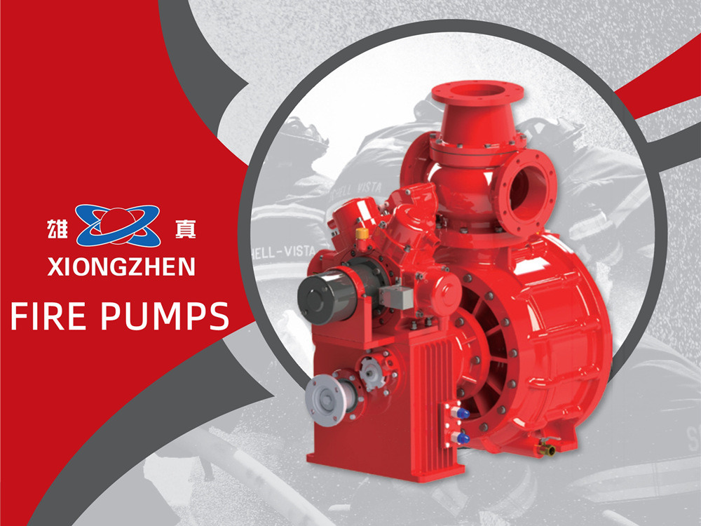
For conventional fire trucks, water is the core medium for fire fighting and rescue. As the core power unit of the complete water supply system on fire trucks, the vehicle-mounted fire pump directly determines the vehicle’s fire suppression efficiency, water supply pressure and sustained operation stability. Xiongzhen has been engaged in the R&D and manufacturing of fire pumps for many years. By integrating mature pump structures at home and abroad and wear-resistant new materials, we have developed a full range of medium-low pressure and high-low pressure vehicle-mounted fire pumps.All products have passed national 3C fire certification and type inspection. Featuring stable water output, fast priming, compact structure and easy maintenance, they are suitable for refitting and supporting various water tank, foam and emergency rescue fire trucks. Xiongzhen fire pumps cover a full range of models: low-pressure pumps including CB10/20, CB10/30, CB10/40, CB10/60, CB10/80, CB10/100, CB10/120 and CB10/140; medium-low pressure pumps such as CB20·10/15·30, CB20·10/20·40, CB20·10/30·60 and CB20·10/40·80; the high-low pressure pump CB40·10/7·50, plus medium-pressure pumps CB20/15, CB20/20 and CB20/30. Each model is supplied with complete performance specifications, optional gear ratios and installation dimensions. Capable of meeting water supply requirements for fire truck refitting and emergency rescue both domestically and overseas, they feature stable performance, simple operation and effortless maintenance. Xiongzhen series fire pumps are mainly assembled from pump body, oil filler, water inlet pipe, check valve, double piston priming device, speed measuring gear, gearbox and input shaft. Medium-low pressure variants are further fitted with pneumatic ball valves for medium-low pressure switching, medium-pressure check valves and low-pressure check valves. The unit adopts an integrally cast aluminum pump casing for even water output. Equipped with a double piston priming mechanism, medium-low pressure pumps offer two drive modes for selection: electric drive and belt pulley drive, delivering fast priming and user-friendly operation. Parameter Comparison of Main Fire Pump Models With different working condition CB10/40 CB10/60 CB10/100 CB10/140 CB20·10/30·60 CB40·10/7.50 CB20/30 Flow(L/s) 40 60 100 140 60 30 30 28 42 70 98 30 21 60 20 30 50 70 30 15 452 --- 35 (Combined low-pressure) 15 30 --- 15 (Combined medium-pressure) --- --- Exit Pressure (MPa) 1.0 1.0 1.0 2.0 1.3 2.0 1.3 1.0 1.0 1.0 1.0 1.3 --- 1.0 (Combined low-pressure) 2.0 1.0 --- 2.0 (Combined medium-pressure) --- --- Rated Speed (rpm) 3135±50 3280±50 2270±50 2600±50 3251±50 2360±50 3145±50 3390±50 3520±50 2320±50 2810±50 3271±50...
Detalles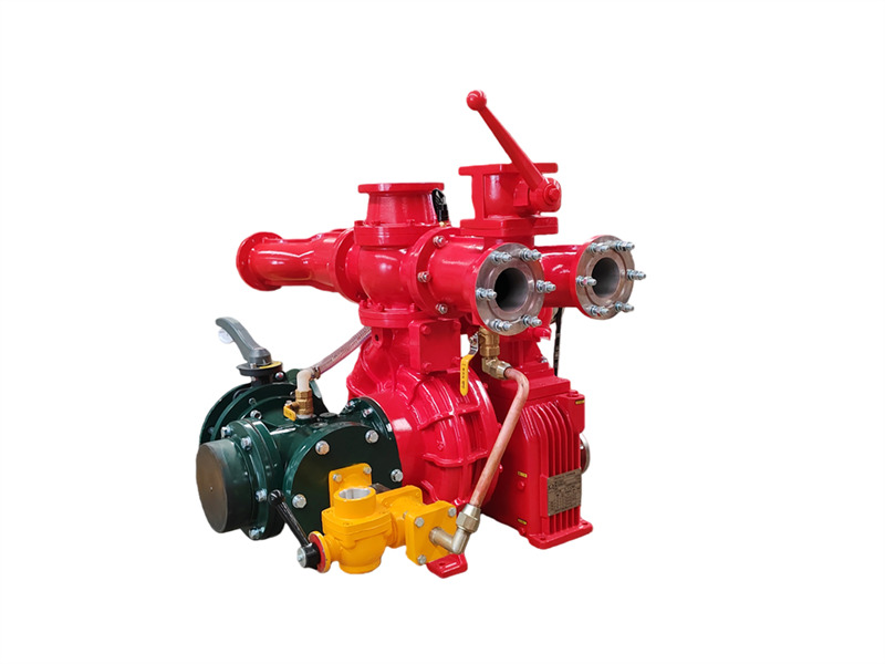
El Bomba contra incendios montada en camión CB10/60-RSconsiste en una bomba centrífuga de baja presión de una sola etapa, una bomba de vacío de doble pistón, un dispositivo de desacoplamiento automático con embrague electromagnético, un reductor de velocidad, una tubería de salida con válvula de cierre y una tubería de entrada. ♦ Estructura principal y función (1) Bomba centrífuga de baja presión de una sola etapa:Compuesta por una cubierta de bomba, carcasa de bomba, impulsor de primera etapa y eje de la bomba, proporciona la presión nominal y el caudal nominal. (2) Reductor de velocidad: El reductor de velocidad de la bomba contra incendios montada en el vehículo CB10/60-RS tiene una relación de aumento de velocidad convencional de 1.440. (3) Bomba de vacío de doble pistón: Principalmente compuesta por un pistón, carcasa de la bomba, eje de la bomba y rueda excéntrica. La rueda excéntrica está equipada con una varilla guía del pistón y un manguito de acero en la carcasa de la bomba. Las válvulas de entrada y salida están instaladas en ambos extremos de la bomba de pistón. Cuando se acopla el embrague electromagnético, la bomba de pistón comienza a funcionar. Durante la operación, el movimiento excéntrico de la rueda excéntrica hace que el pistón se mueva de manera recíproca, expulsando gradualmente el aire de la bomba y de la tubería, mejorando así la calidad del aire. Se crea un vacío dentro de la cavidad para lograr el propósito de succión de agua. 1. Válvula de cierre de salida (4 piezas); 2. Tuberías de salida de agua izquierda y derecha; 3. Conector de retorno de agua de enfriamiento de la caja de engranajes; 4. Conector del manómetro; 5. Válvula de retención de salida; 6. Brida del cañón de agua; 7. Interruptor de presión de agua; 8. Conector de retorno de agua de presión de enfriamiento del PTO; 9. Brida del tanque de agua trasero; 10. Válvula esférica del tanque de agua trasero; 11. Caja de engranajes; 12. Embrague electromagnético y cableado; 13. Bomba de cebado de pistón; 14. Conector del manómetro de vacío; 15. Conector de cebado de vacío; 16. Interfaz de la tubería de entrada; 17. Tubería de entrada de cuatro vías; 18. Válvula de drenaje de la bomba de agua; 19. Tubería de retorno de agua de presión de enfriamiento de la caja de engranajes; 20. Tubería de entrada de agua de presión de enfriamiento de la caja de engranajes; 21. Válvula de nivel de aceite lubricante de la caja de engranajes; 22. Brida de acoplamiento; 23. Correa de transmisión; 24. Conector roscado de agua a presión del dosificador de espuma (no disponible en camiones cisterna de agua); 25. Interfaz del dosificador de espuma; 26. Conector de salida de agua de presión de enfriamiento del PTO; 27. Bomba contra incendios del vehículo CB10/60; 28. Conector de salida de agua de presión de enfriamiento de la caja de engranajes; 29. Válvula mariposa de entrada trasera (4) Tubería de salida de agua de baja presión y válvula de cierre:Consta...
Detalles
POWERSTAR is a professional fire truck manufacturer and exporter. Our product range includes water tank fire trucks, foam fire trucks, dry powder fire trucks, and aerial ladder fire trucks, widely used in urban firefighting, petrochemical plants, airports and seaports, forest fire protection, and more. Our fire truck models based on ISUZU, HOWO, and FAW chassis are exported to many countries and regions across Southeast Asia, the Middle East, South America, and Africa. From bulk procurement by the Philippine government to repeat orders from Nigerian clients, POWERSTAR has earned a strong reputation among global customers through reliable quality and professional customization services. Why does POWERSTAR choose XIONGZHEN fire pumps?The fire pump is often called the "heart" of a fire truck—without a highly efficient and reliable fire pump, a fire truck is merely a vehicle for transporting equipment and personnel, unable to truly accomplish firefighting missions. For this very reason, POWERSTAR adheres to the highest standards when selecting core components.XIONGZHEN is a well-known brand in China's fire pump industry, with its products widely used by many professional fire truck manufacturers across the country. Built upon advanced technologies from Germany, Austria, the United States, and other countries, combined with independent R&D strengths, XIONGZHEN offers vehicle-mounted fire pump series whose performance rivals imported products. Key advantages include:• Excellent performance and high efficiency: The two-stage centrifugal impeller and guide-vane pump casing design balance radial and axial forces on the pump shaft, ensuring smooth and efficient operation.• Compact structure and simple operation: The integrated design of the guide-vane chamber and pressure chamber makes maintenance and servicing convenient.• Innovative priming technology: A four-piston electric priming pump with an electromagnetic clutch delivers greater water intake and superior suction performance compared to traditional two-piston pumps, effectively preventing dry-running damage to mechanical seals under no-water conditions.• Authoritative certification: The entire product line has passed type testing by the National Fire Equipment Quality Supervision and Inspection Center and complies with the GB6245-2006 standard. POWERSTAR chooses XIONGZHEN fire pumps precisely because of their reliable quality and proven technology, ensuring that every fire truck leaving our factory performs consistently and dependably in firefighting and rescue missions around the world.XIONGZHEN Fire Pump Full Series – Specifications & Selection GuideXIONGZHEN fire pumps offer a complete range of low-pressure and medium-low-pressure products, suited for fire trucks of different tonnages and applications. Below are the technical parameters for some key models: Model Working Condition Flow (L/s) Outlet Pressure (MPa) Rated RPM (r/min) Shaft...
Detalles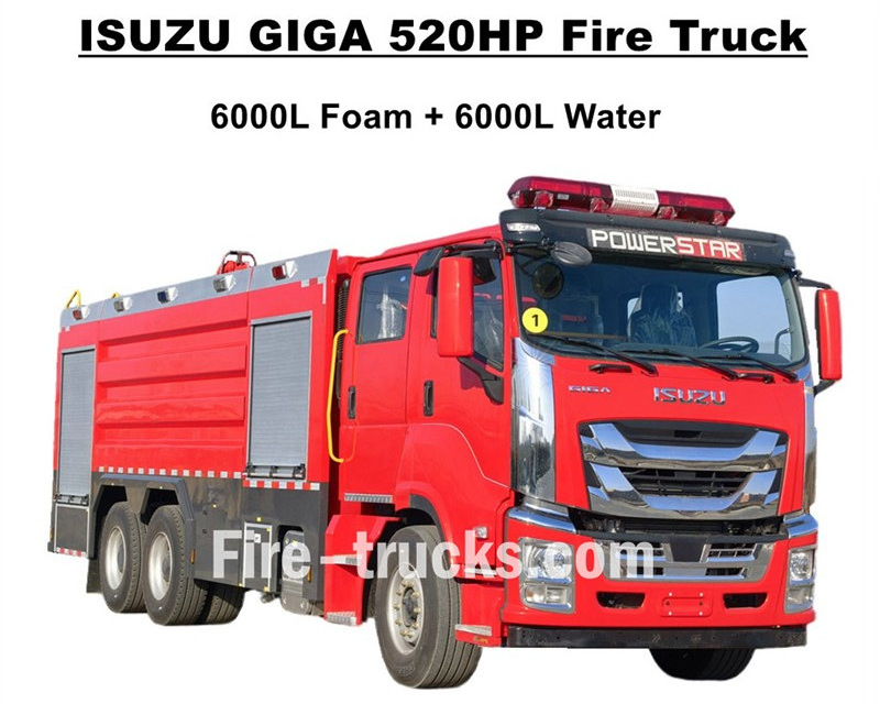
Máxima calidad Camiones de extinción de incendios ISUZU GIGA exportados a África Occidental, Burkina Faso, diseñados sobre el chasis de camión pesado ISUZU GIGA VC66 6x4, adoptan la nueva cabina GIGA VC66, asiento con suspensión neumática estándar y aire acondicionado para una conducción cómoda. El camión está equipado con un motor diésel de tecnología japonesa ISUZU modelo 6WG1-TCG62, de 520 HP y una cilindrada de 15681 cc, combinado con una caja de cambios manual FAST de 12 velocidades, con un consumo de combustible muy bajo, neumáticos delanteros estándar 385/80R22.5 y traseros 315/80R22.5, con un total de 10+1 unidades. Los kits de carrocería superior incluyen un tanque de agua de 6000L y un tanque de espuma de 6000L, ambos fabricados con material de acero inoxidable #304, duradero para un servicio de larga vida útil. Combinado con una bomba contra incendios CB10/140 personalizada de gran potencia con un caudal eficiente de 140L/s, equipada con una doble bomba contra incendios en la parte superior del kit de carrocería del tanque, con modelo PL8/64 y un caudal eficiente de 64L/s. Camión de bomberos ISUZU GIGA 520HP equipado con todos los equipos necesarios para la lucha contra incendios, que es un camión de bomberos ideal para la extinción de incendios y el rescate de personas, y se utiliza ampliamente en el mercado de Burkina Faso. Camión de bomberos cisterna de espuma ISUZU GIGA 520HP 14,000L Fábrica CS TRUCKS es un fabricante profesional en el área de camiones,garantiza que todos los productos sean nuevos y de alta calidad. Características del camión de bomberos ISUZU: Nombre Camión de bomberos con bomba de espuma ISUZU GIGA 12000L Cabina GIGA VC66 Motor 6WG1-TCG62 con 520HP y cilindrada de 15681cc Transmisión FAST de 12 velocidades Distancia entre ejes 4600+1370mm Neumático Delantero: 385/80R22.5 (2 unidades) Trasero: 315/80R22.5 (8 unidades) Tanque Tanque de espuma de 6000L (acero inoxidable #304) Tanque de agua de 6000L (acero inoxidable #304) Bomba contra incendios CB10/140 con caudal de 140L/s Monitor contra incendios Delantero: PL8/64 con caudal de 64L/s Trasero: PL8/64 con caudal de 64L/s Equipamiento Juegos completos de equipos contra incendios personalizados Cómo operar un camión de bomberos con tanque de espuma ISUZU: .
Detalles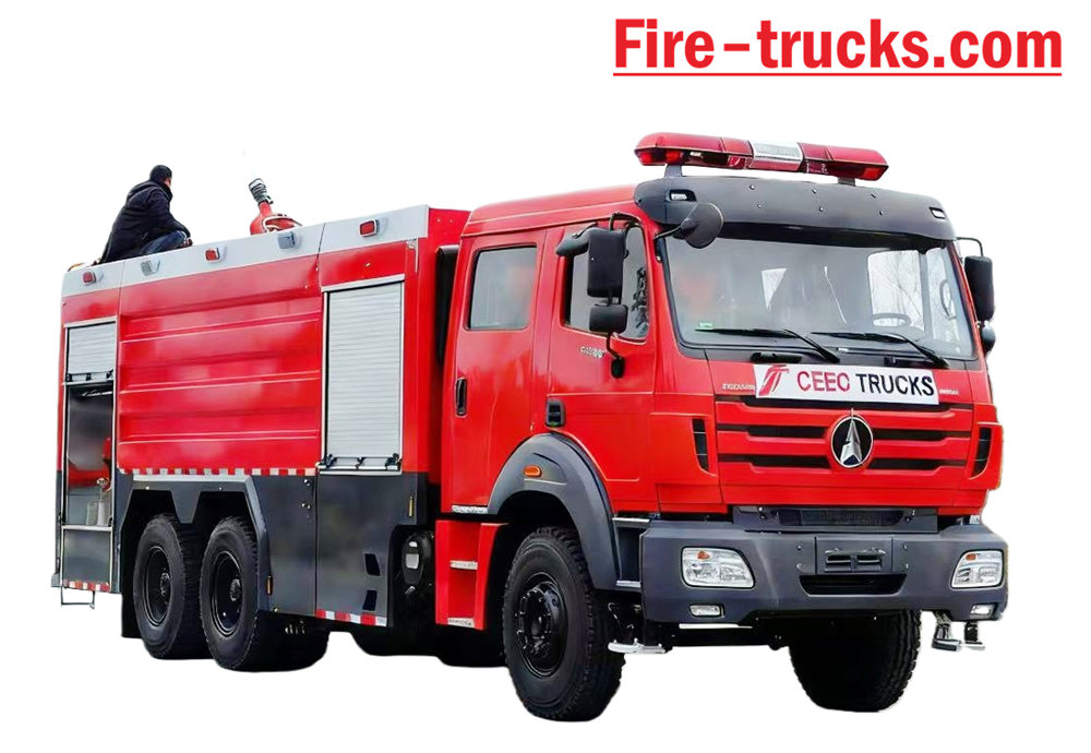
Beiben Camión de bomberos basado en el chasis y carrocería Beiben 2638 tipo II, modelo 6*4, con volante a la izquierda. La capacidad podría llegar hasta 12.000 litros, incluyendo un tanque de agua de 10.000 litros y un tanque de espuma de 2.000 litros. Rescate de incendios de Beiben 2638 camión equipado con bomba contra incendios XIONGZHEN CB10/60 y monitor de incendios PL8/48, muy conveniente para Uso diario. Se utiliza principalmente para proyectos de extinción de incendios en cualquier zona que lo necesite. El vehículo fue diseñado para aprovechar al máximo las ventajas del chasis original del camión de la marca Beiben. Considere plenamente la conveniencia y confiabilidad del producto, así como el chasis de nuevo diseño. La carrocería El material es acero al carbono estándar internacional con pintura anticorrosión y acero inoxidable, que Puede ser eficaz para evitar la oxidación y garantizar una larga vida útil. El camión de bomberos Beiben 6x4 está equipado con toma de fuerza tipo sándwich, bomba contra incendios, monitor de incendios, sala de tripulación y manguera. caja, sala de bombas, tanque de polvo seco y sistema de nitrógeno, acoplado a carrete de manguera de tubería, inglés caja de control de versiones, tubería de entrada y salida, escalera de ascenso trasera, lámpara de almohada superior y todo lo necesario Equipo de extinción de incendios. Cabina personalizada de doble fila con 2+4 asientos, agradable sensación de conducción. Por lo tanto, el Este vehículo es un camión de bomberos ideal, principalmente para proyectos de extinción de incendios. [if gte mso 9]> Normal 0 7.8 磅 0 2 false false false EN-US ZH-CN X-NONE
Detalles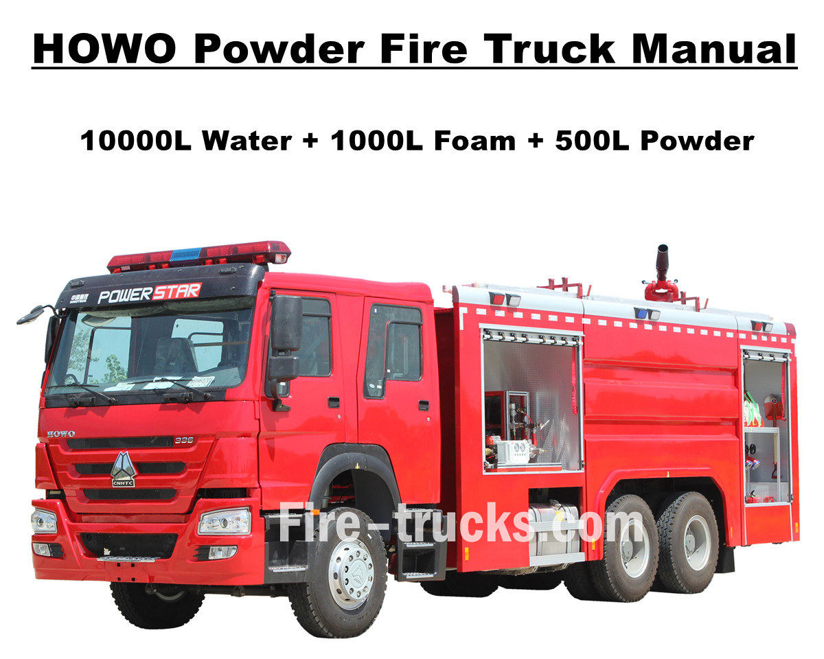
Cliente de África Mauritania compró en total 4 unidades Camión de bomberos autobomba Sinotruk HOWO De POWERSTAR TRUCKS, utilizado en la capital, Nuakchot. Este camión de bomberos, también conocido como camión de bomberos o autobomba, está diseñado y fabricado para satisfacer las necesidades de múltiples proyectos internacionales de extinción de incendios y rescate de personas. Dispone de cabina doble personalizada para el transporte de bomberos, diversos equipos y herramientas de extinción de incendios, rescate, etc. Para garantizar la mayor eficiencia de los camiones de bomberos HOWO, los hemos adaptado para que estén equipados con escaleras de aleación de aluminio, tanques cisterna para agua, espuma y agente extintor de polvo seco, bomba contra incendios CB10/60 de alta eficiencia con monitor de incendios PL8/48 y alcance de pulverización superior a 70 m, carrete de manguera con pistola para extinción de incendios a larga distancia, equipo de respiración con máscara, ropa protectora, herramientas de rescate, botiquín de primeros auxilios, etc. Todos los servicios para camiones de bomberos HOWO garantizan un trabajo eficiente y confiable. Para garantizar que los clientes de Mauritania utilicen el camión de bomberos HOWO de forma más fácil y eficiente, todos los camiones vienen equipados con un catálogo completo en versión en inglés para el servicio, que incluye el Manual del usuario para orientación sobre el funcionamiento, el Manual del camión y el Manual de repuestos para su uso y mantenimiento. Camión de bomberos con bomba de polvo SINOTRUK HOWO de 14.000 l Fábrica de POWERSTAR es fabricante profesional en el área de camiones, Garantizamos todos los productos nuevos y de alta calidad. » Ⅰ. Ventajas del camión de bomberos HOWO: ★ Potente motor diésel WEICHAI de 247KW / 336HP, 100.000 Km sin problemas. ★ SINOTRUK HOWO cabina clásica HW76, diseño europeo ★ Bomba contra incendios CB10/60 montada, caudal de 60L/s, súper confiable ★ Cañón de agua PL8/48 montado en la parte superior, servicio duradero ★ 500L de polvo seco con botella de nitrógeno, con válvulas de control de aire ★ Sistema de control integrado para espuma y polvo, con panel en la parte trasera » Ⅱ . Dibujo del camión de bomberos de rescate de Howo: [si gte mso 9]> Normal 0 7.8 veces 0 2 falso falso falso EN-US ZH-CN AR-SA /* Style Definitions */ table.MsoNormalTable {mso-style-name:普通表格; mso-tstyle-rowband-size:0; mso-tstyle-colband-size:0; mso-style-noshow:yes; mso-style-priority:99; mso-style-parent:""; mso-padding-alt:0cm 5.4pt 0cm 5.4pt; mso-para-margin:0cm; mso-pagination:widow-orphan; font-size:10.0pt; font-family:"Calibri",sans-serif; mso-bidi-font-family:"Times New Roman";} To guarantee Mauritania Nouakchott clients purchased satisfy HOWO 6x4 Water & Foam & Powder Fire Truck, so we POWERSTAR Engineer Department do design the truck firstly, then start for production. Howo fire truck equipped with Sandwich PTO, fire pump, fire monitor, crew room, hose box, pump room, English ve...
Detalles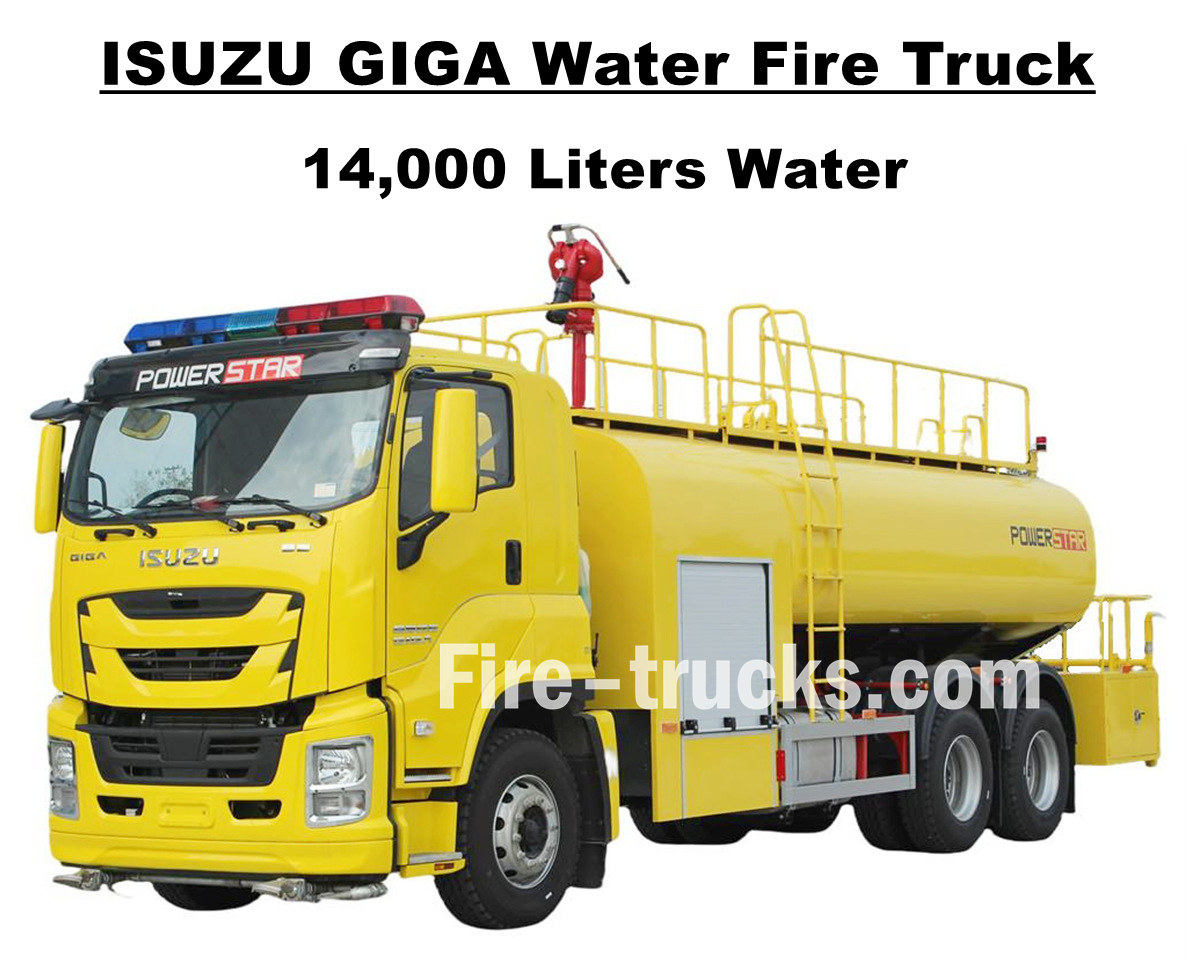
Cliente sudamericano Sr. Joseph de Honduras, quien compró 1 unidad Camión contra incendios Isuzu GIGA VC66 de 14.000 litros y 3.700 galones de POWERSTAR TRUCKS, Diseñado con el chasis del camión pesado japonés ISUZU GIGA 6x4, equipado con un motor diésel 6UZ1-TCG60 de 280 kW / 380 HP, de 6 cilindros, 4 tiempos, refrigerado por agua, turboalimentado e intercooler, con una cilindrada de 9839 ml. Incorpora una caja de cambios manual FAST de 12 velocidades, estándar internacional, con 12 marchas hacia adelante y 2 hacia atrás, lo que reduce el consumo de combustible. Incorpora 13 neumáticos de acero 12R22.5, incluyendo uno de repuesto. Ideal para diversas condiciones de carretera y para escalar montañas. La distancia entre ejes puede ser de 4600 + 1370 mm. Servicio diseñado conveniente y adecuado para proyectos de extinción de incendios para múltiples áreas. El camión cisterna de agua Isuzu GIGA de 3700 galones se basa completamente en el chasis de camión ISUZU de tecnología japonesa, el gabinete GIGA VC66 original equipado con aire acondicionado con función de calefacción y refrigeración para una conducción cómoda. Y montado en el camión con carrocería de acero inoxidable SS304, con un volumen eficiente de 14000 litros, equivalente a 3700 galones, equipado con una bomba contra incendios CB10/60 de marca china y un monitor de incendios PS8/50 en la parte superior de la carrocería del camión, conjuntos completos de equipo de rescate contra incendios y pintura amarilla limón personalizada para todo el camión, todo lo cual hace del camión un vehículo ideal para proyectos de extinción de incendios en las calles y comunidades de Honduras. Además, el camión se combina con conjuntos completos de catálogo en versión en inglés para el servicio, que incluye el Manual del usuario para la guía de operación, el Manual del camión para el uso del camión GIGA y el Manual de repuestos para el mantenimiento. Camión de bomberos con bomba de agua Isuzu GIGA de 14.000 l Fábrica de POWERSTAR es fabricante profesional en el área de camiones, Garantizamos todos los productos nuevos y de alta calidad. » Ⅰ. Ventajas del camión de bomberos acuático Isuzu: ★ Potente motor diésel 6WG1 de 280KW / 380HP, 100.000 Km sin problemas. ★ ISUZU VC66 nueva cabina GIGA, diseño europeo ★ Bomba contra incendios CB10/60 montada, caudal de 60L/s, súper confiable ★ Cañón de agua PS8/50 montado en la parte superior, servicio duradero ★ Sistema de control integrado, con panel lateral ★ Pintura personalizada de color amarillo limón, brillante y hermosa. Bomba contra incendios CB10/60 Modelo : CB10/60 Presión : 1.0Mpa Presión máxima de trabajo : 1.232 Mpa Caudal : 60 L/s a 1,0 Mpa, velocidad 3286 ± 50 r/min, potencia 102 kW, profundidad de succión 3 m 42 L/s a 1,3 Mpa, velocidad 3519 ± 50 r/min, potencia 106 kW, profundidad de succión 3 m 30 L/s a 1,0 Mpa, velocidad 3120 ± 50 r/min, potencia 73 kW, profundidad de succión 7 m Relación de velocidad : 1:1.44 Monitor de incendios PS8/50 Modelo : PS8/50...
Detalles
Powerstar Trucks fabrica vehículos de respuesta a emergencias personalizados y Camiones de bomberos Durante varios años, Powerstar Trucks Emergency Response ha establecido su legado como el fabricante líder de línea completa de aparatos contra incendios personalizados con experiencia en camiones de bomberos con agua y espuma y vehículo de rescate de bomberos Basándose en el legado en el que confían los bomberos, los camiones Powerstar ofrecen soluciones flexibles, estratégicas y especializadas para satisfacer las necesidades únicas de cada departamento de bomberos, priorizando a los socorristas. 120 unidades Camión de bomberos de rescate para entrega Exportación de 65 unidades de camiones de bomberos de rescate a la Policía de Uganda Camiones de bomberos de agua Vehículo de extinción de incendios con espuma Los camiones de bomberos se clasifican principalmente en cuatro categorías según su función: camiones de bomberos, camiones de escalera aérea, camiones de bomberos para fines especiales y camiones de bomberos de apoyo logístico. 01, camiones de bomberos son la principal fuerza para la extinción directa de incendios, entre ellos: **Camiones de Bomberos con Tanque de Agua:** Equipados con su propio tanque de agua y bomba, adecuados para extinguir incendios en general. **Camiones de bomberos de espuma:** Diseñados específicamente para extinguir incendios que involucran líquidos inflamables como el aceite. **Camiones de bomberos de polvo seco:** Adecuados para extinguir incendios de gas y eléctricos. **Camiones de bomberos de dióxido de carbono:** Se utilizan para proteger equipos valiosos e instrumentos de precisión. **Camiones de uso combinado de espuma y polvo seco:** Pueden utilizar ambos agentes extintores simultáneamente, con una amplia gama de aplicaciones. 02, Camiones de bomberos con escalera aérea Se utilizan para rescate y extinción de incendios en edificios de gran altura, incluyendo principalmente: **Camiones de Bomberos con Escalera**: Equipados con escalera telescópica, capaces de rescatar personas y extinguir incendios en altura. **Camiones de bomberos con pulverización aérea:** Utilizan un brazo controlado a distancia para pulverizar agentes extintores a largas distancias. **Camiones de bomberos con plataforma aérea:** Proporcionan una plataforma elevadora hidráulica para rescate y extinción de incendios. Solicitud de camión de bomberos 03, Los camiones de bomberos especializados son responsables de tareas específicas, tales como: **Camiones de bomberos para rescate y socorro en caso de desastre:** Equipados con herramientas de demolición y equipos de elevación, se utilizan para rescate en caso de accidentes. * **Iluminación de camiones de bomberos:** Proporciona iluminación de alta intensidad para operaciones de rescate nocturnas. **Camiones de bomberos con extracción de humo:** Se utilizan para operaciones de extracción de humo en incendios subterráneos. 04, **Camiones de bomberos de apoyo logístico:** Proporcionan principalment...
Detalles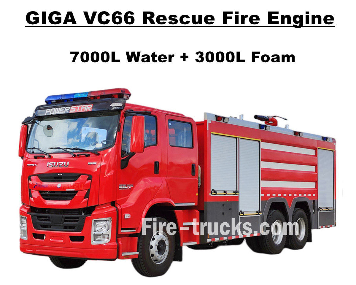
Los clientes de Manila, Filipinas, compraron Camión de bomberos de servicio pesado Isuzu GIGA VC66 de POWERSTAR TRUCKS, que está equipado con un motor diésel japonés ISUZU 6WG1-TCG61 con una potencia de 338 kW / 460 HP, que es un motor de 6 cilindros, 4 tiempos, refrigerado por agua, turboalimentado e intercooler, con un desplazamiento diseñado de 15681 cc estándar, combinado con una caja de cambios manual FAST 12 estándar internacional, 12 cambios hacia adelante y 2 cambios hacia atrás, un consumo de combustible muy bajo, 13 unidades de neumáticos sin cámara totalmente instalados con el modelo 315 / 80R22.5, incluido un neumático de repuesto, muy adecuado para varios tipos de condiciones de la carretera. y servicio para proyectos de extinción de incendios en múltiples áreas. Confíe completamente en el chasis original del camión ISUZU GIGA VC66, modifique la cabina de doble fila GIGA con asientos delanteros normales 2+1 y traseros 4 asientos SCBA, en la cabina equipada con aire acondicionado con función de calefacción y refrigeración para una conducción cómoda. Y camión montado con carrocería cisterna de material SS304 de acero inoxidable completo, equipado con una bomba contra incendios XIONGZHEN CB10/60 de la marca china Top en la sala de bombas trasera, combinado con el monitor de incendios WESTER PL8/48 en la parte superior de la carrocería del camión cisterna, conjuntos completos de equipo de rescate contra incendios, todo hace del camión un vehículo ideal para proyectos de extinción de incendios en la calle y la comunidad de Manila. También el camión se combina con conjuntos completos de catálogo de la versión en inglés para el servicio, que incluye el Manual del usuario para la guía de operación, el Manual del camión para el uso del camión GIGA, el Manual de repuestos para el mantenimiento. Camión contra incendios Isuzu de 7.000 litros de agua y 3.000 litros de espuma Fábrica de POWERSTAR es fabricante profesional en el área de camiones, Garantizamos todos los productos nuevos y de alta calidad. » Ⅰ. Características principales del camión de bomberos Isuzu 6WG1: ★ Potente motor diésel 6WG1 de 338KW / 460HP, 100.000 Km sin problemas. ★ ISUZU VC66 nueva cabina GIGA, diseño europeo ★ Cabina de doble fila, con 4 asientos traseros SCBA ★ Bomba contra incendios CB10/60-XZ montada, caudal de 60 L/s, súper confiable ★ Cañón de espuma PL8/48 montado en la parte superior, servicio duradero ★ Sistema de control integrado, con panel en la parte trasera Bomba contra incendios CB10/60-XZ Modelo : CB10/60-XZ Presión : 1.0Mpa Presión máxima de trabajo : 1.232 Mpa Caudal : 60 L/s a 1,0 Mpa, velocidad 3286 ± 50 r/min, potencia 102 kW, profundidad de succión 3 m 42 L/s a 1,3 Mpa, velocidad 3519 ± 50 r/min, potencia 106 kW, profundidad de succión 3 m 30 L/s a 1,0 Mpa, velocidad 3120 ± 50 r/min, potencia 73 kW, profundidad de succión 7 m Relación de velocidad : 1:1.44 Monitor de incendios PL8/48 Modelo : PL8/48 Presión : 0,8 Mpa Rango de trabajo : Espuma ≥ 70m...
Detalles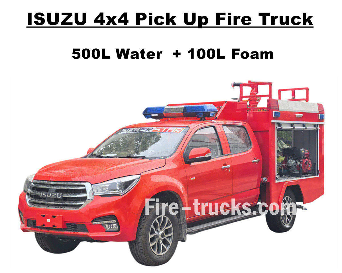
Venta de fábrica Camión de bomberos todoterreno ISUZU 4x4 El camión de bomberos ISUZU TAGA, con tracción en las cuatro ruedas, integra un excelente sistema de potencia para afrontar todo tipo de terrenos difíciles. Está equipado con un conjunto completo de cisterna de acero inoxidable SS304, que incluye un tanque de agua de 500 litros y un tanque de espuma de 100 litros, y una bomba contra incendios independiente profesional JBQ4.5/9, montada en la sala de bombas trasera, con gran alcance de pulverización y panel de control con idioma opcional. También ofrece diversas configuraciones opcionales para satisfacer diferentes necesidades, incluyendo un monitor de incendios PS20 montado en la parte superior para chorro de agua. Este camión de bomberos ISUZU Pickup de 143 HP ofrece una sólida garantía de seguridad contra incendios y demuestra un excelente rendimiento y flexibilidad. La cabina original de doble fila del camión de bomberos Isuzu ofrece suficiente espacio y calidad para cargar equipo contra incendios y mantener un buen rendimiento de conducción. La cabina tiene capacidad para 5 bomberos y está equipada con aire acondicionado para garantizar la comodidad del conductor en cualquier condición climática. Todo esto garantiza que el camión de bomberos de espuma ISUZU de 600 L sea un vehículo de rescate ideal para el mercado albanés. A continuación se detalla el Manual del Usuario para una operación y trabajo seguros. » Ⅰ. Características principales del camión de bomberos Isuzu Pick Up: ★ Potente motor 4KH1 de 105KW / 143HP, 100.000 Km sin problemas. ★ ISUZU TAGA nueva cabina pickup, diseño europeo ★ Cabina doble original, adecuada para 5 bomberos. ★ Bomba contra incendios independiente JBQ4.5/9, súper confiable ★ Cañón de fuego PS8/20 montado en la parte superior, servicio duradero » Ⅱ. Resumen de la recogida de bomberos: El camión de bomberos ISUZU 4x4 todoterreno con tracción total y espuma de agua es un vehículo todoterreno de rescate que presta servicio en diversas áreas, como comunidades, bosques, fábricas, etc. Gracias a su capacidad todoterreno y su diseño compacto, este camión de bomberos Isuzu Pickup puede cumplir con éxito múltiples misiones. Para que nuestros camiones de bomberos sean más adecuados, a continuación se presentan opciones para diferentes clientes. ----- Material de cisterna : Acero al carbono, acero inoxidable, aleación de aluminio, material PP ----- Bomba contra incendios : En función del cuerpo del petrolero y la distancia de propulsión, opción americana Darley marca ----- Opcional: Tubería, carrete de manguera, escalera de aluminio, modelo conjunto (tipo chino, europeo, americano) » III. Aspecto atractivo: El camión de bomberos ISUZU 4x4 AWD es potente y ágil, alcanza rápidamente el lugar del incendio y atraviesa terrenos complejos con facilidad. Su cañón superior ofrece un amplio alcance y un gran caudal, y su carrete de manguera contra incendios de 50 m con cañón permite alcanzar con precisión el foco del incendio,...
Detalles
Por favor, siga leyendo, manténgase informado, suscríbase, y le invitamos a que nos diga qué piensa.

 Network IPv6 compatible con

 español
 English
 français
 Deutsch
 русский
 italiano
 português
 Nederlands
 العربية
 日本語
日本語 한국의
한국의 Türkçe
 Melayu
 ไทย
ไทย Tiếng Việt
 Indonesia
  中文
中文 қазақ
қазақ Filipino
 မြန်မာ
 српски